Automated Steel Shaft Cutter

I designed and built two advanced prototypes for an automated shaft-cutting machine based on a client's specific needs. This project was for my Senior Design class at Tufts University and I worked on it with Greg Osha, Gordian Liao, and Chris Tilton.
The automated steel shaft cutter allows engineers to run a single cutting operation on a 3-10 mm shaft autonomously, enabling them to spend more time on design instead of manufacturing. Through a simple-to-use interface, the user can input a desired steel shaft length and work on other designs while the cutting operation runs. This product would be a useful workbench machine for any prototyping engineer.
Skills
User-Centered Design, Client Engagement, Project Management, PCB design, Advanced CAD Assemblies, High-Fidelity Prototypes, DFMA
User and Market Analysis
Based on conversations with our client, from REEKON Tools, we identified and ranked a list of user needs. We formalized these needs into engineering requirements for our project. These requirements guided all of our major design decisions and helped us evaluate the success of each finalized prototype.

Before diving into mechanical design, we evaluated existing solutions for cutting steel shafts against our engineering requirements and analyzed the technical aspects of each that seemed desirable for our application.

Ideation and Design Decisions
Our primary method of ideation and concept generation was morphologies. We broke down the entire shaft-cutting process into sub-tasks:
- Measure the desired shaft length
- Move the shaft into place
- Clamp the shaft
- Spin the blade
- Move the blade
- Blade type
Next, we thought of ways we could accomplish each task. When it came to choosing methods, some options made a lot of sense to combine, like the spring-loaded clamps and a vertically actuating cutting system. The harder choices required a more extensive decision matrix, like how we would move the cutting blade into the shaft.
The highlighted methods below are the ones we chose based on downselection and evaluation against our engineering requirements.

Prototyping

Our first prototype features 3 stepper motors attached to lead screws, a high-power DC motor with an abrasive cutting blade, and a v-shaped slot to hold the shafts. We fabricated it with a combination of custom 3D prints and aluminum waterjet, off-the-shelf components, and an aluminum 80-20 frame.
We modeled the whole assembly on Onshape and focused on making a robust CAD document capable of handling large revisions. You can explore the CAD here. Working on a team of 4, it was extremely important for us to track our revisions and be intentional with our CAD practices. I appreciated the value of this more after working on the second prototype.


These videos show the movement of the shaft into place for cutting (left) and the spring clamp's actuation (right). We counted stepper motor steps to get an accurate travel distance.
Overall this was a promising prototype. We saw potential in the movement of the shafts as well as the abrasive cutting method. This prototype lacked ways to locate the position of the motors beyond counting steps (there was no ability to return to a zero position), and we desired more rigidity in the cutting and clamping process. Because of the early success we had in this project, we strove for quality in the second prototype.

Prototype 1

Prototype 2
The major changes we made from version #1 to version #2:
Safety
-
Added a polycarbonate safety housing
-
Improved construction stability
-
Added an emergency stop button integrated into the circuit
Cutting
-
Lighter clamp springs
-
Added a 2nd clamp to balance forces
Accuracy
-
Added limit switches for each stepper motor to create a zero position
Automated
-
Integrated a control interface with a graphical screen
Compact
-
Flipped orientation of the stepper motors
-
Created a custom PCB to improve the wiring


I did the electrical layout for this project and designed this PCB to interface with the microcontroller, the high-power input, and the cutting motor. We ordered it from OSH Park and used it, with success, in our final prototype. One safety consideration I evaluated was making sure the system could handle the high current of the cutting motor, which I determined drew a maximum current of 20 amps. I calculated the trace thickness to handle this and ended up placing traces on both sides of the PCB for the high current path.


Above shows a measured shaft using the REEKON T1 that we cut on our machine. Once we calibrated the stepper motors, we achieved our desired tolerance of ± 1mm Because we used an abrasive cutter, the cuts came out relatively dull and the parts were ready to be used.
_HEIC.png)
Below is the full design report including the technical drawing package

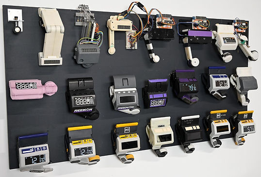
In reflecting with my teammates, although we were proud of the work we did, we had hoped for a more polished product at the end of the semester, similar to REEKON's devices. However, I thought back to our visit to the REEKON office where they proudly displayed each of their 20+ prototypes for their first product. This reminded me that engineering is a constant force of improvement, where every iteration brings you closer to a better solution. It reinforced the importance of perseverance, learning from each version, and embracing the iterative process.
Overall this project was a great success. My team and I got the opportunity to combine design practices and technical engineering skills from multiple disciplines to create a successful tool that fits our client's requirements.
I particularly appreciated the opportunity to create two, high-quality, stand-alone prototypes because it enabled us to implement drastic improvements and more easily compare changes. Practicing design review presentations and meeting with our client every other week were also great people-facing engineering experiences.